Heating Programmer Wiring Diagram
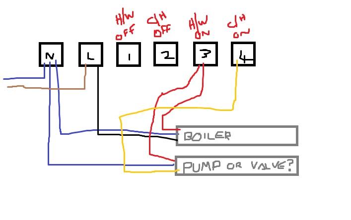
It could be a fix as the hw operates as it should. Power starts at terminal 3 (hw on) in the programmer.
Central Heating Programmer Information About Universal & Complicated
No turn knob to 60°c eys check boiler is the boiler on?

Heating programmer wiring diagram. Wiring diagram for s plan central heating system 2017 hive. New programmer i am installing is a horstmann c27. Numbered wiring diagrams provided in the honeywell wiring guide.
Notes some ac systems will have a blue wire with a pink stripe in place of the yellow or y wire. The diagram set includes wiring plans for a number of popular configurations of central heating systems, c plan, w plan, y plan, s plan, s plan+ etc. Power starts at terminal 4 (ch on) in the programmer.
Configure the programmer if there’s a programmer that controls hot water and heating, set. Electrical wiring for central heating systems. The wiring diagram shows an external pump.
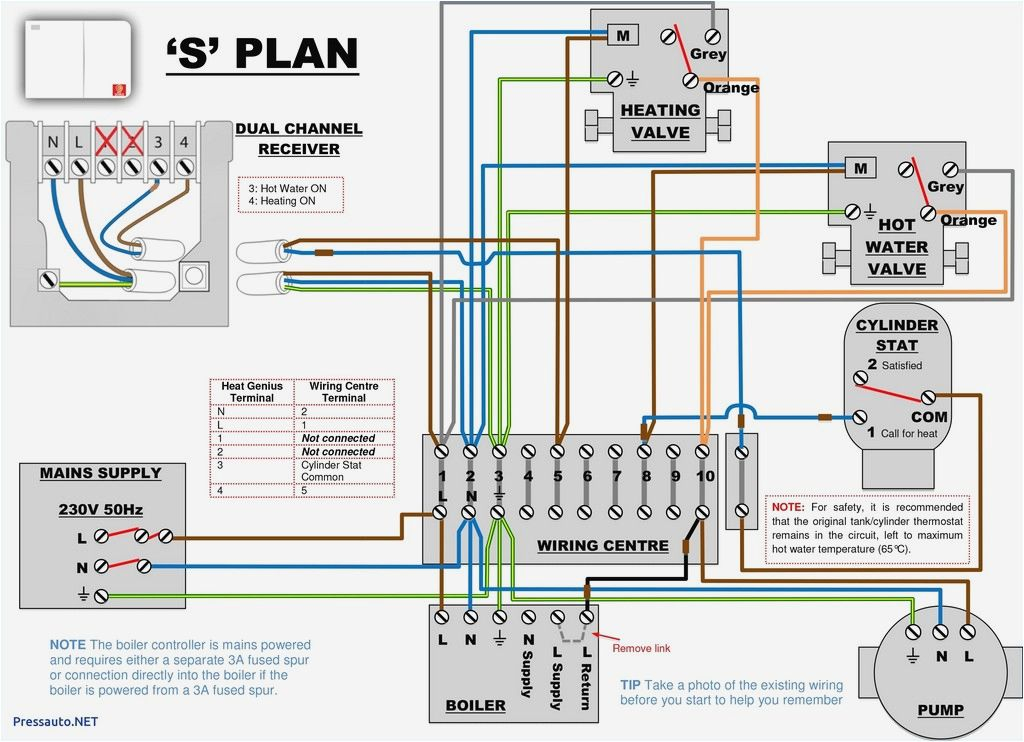
Oct 24, · hi i have a honeywell honeywell st programmer on my central heating system that may be giving me problems: Contains all the essential wiring diagrams across our range of heating controls. If heat is required, power continues to terminal 5 in the wiring centre, and operates the motor in the central heating valve.
So back to the other y plan. The hot water and heating came on fine, but the programmer was not even on. It can also be adapted for use with underfloor heating.
Probably the highest number of requests drayton's technical team receives every week is for help with wiring diagrams using the lwc1 or lwc3 wiring centre. Control wiring for combination boilers thermostats for combination boilers external programmers for combination boilers combination boiler with 2 heating zones, 230v switching combination boiler with 2 heating zones, volt. N, l, 1, 2, 3 and 4.
Central heating wiring diagram y plan. Contains all the essential wiring diagrams across our range of heating controls. New programmer has standard 6 terminals:
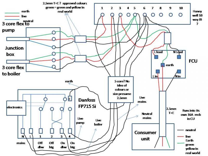
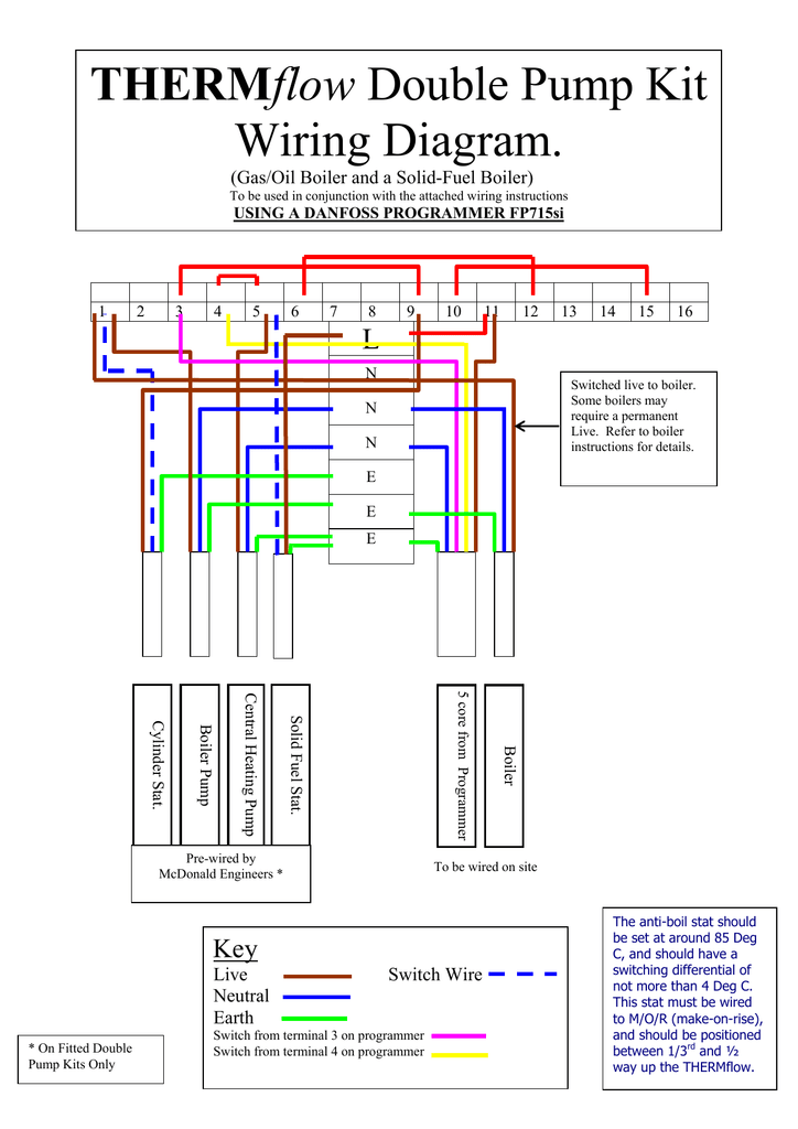
Danfoss fp715si programmer wiring diagram. Worcester bosch combi greenstar with zone valves wiring diagram.the fp si can be configured by the installer at time of installation to provide 7 day, 24 hour, or 5 day/2 day operation and to provide either 2 on/off's. Live live neutral neutral 3 4 4 na 5 na 6 3 7 1 8 na.
Tssi timeswitch no additional wiring diagram for the underfloor heating is required. Showing flow from boiler, up to s plan valves, or zone valves, then onto heating and hot water circuit. If using the st to replace other honeywell programmers, the equivalent wiring terminations are refer to honeywell for wiring conversion diagrams.
No check fuse in fused spur eys check cylinder thermostat is the stat set to a temperature of 60°c? This specific graphic (wiring diagram for s plan heating. Wiring centre contents programmer zone valve heating zone valve hot water room thermostat cylinder thermostat lwc 1 wiring centre heating control pack with switchmaster lifestyle or tempus programmer installation and wiring guide 1 0 20 3 0 o o o oo o o o o o 86mm 37mm 86mm first fix diagram lwc 1 wiring centre.
Honeywell thermostat installation and wiring duration. The fp can be configured by the installer at time of installation to provide 7 day 24 hour or 5 day/2 day operation and to provide either 2 on/off's or 3. Heating controls wiring guide issue 17.
17 years old and consists of a honeywell st programmer, honeywell wiring centre, i need a wiring diagram for a lp used in conjuction with.5/5. This passes via the wiring centre terminal 4 to the room thermostat. The diagrams below show typical wiring circuit's with which the wiring conversionsto be used when replacing the following programmers with the fp, cp.
Click the icon or the document title to download the pdf. Is the red light by the water switch on? Once the valve is fully open, a switch inside connects the grey and orange wires together.
Wiring diagrams and other information for central heating control systems. Oil fired boiler wiring diagram. Programmer 78 9 10 if using a 6 wire or 1” bsp v4043h on either circuit, the white wire is not needed and must be made electrically safe.
St9400c temperature controller pdf manual download. The rayburn is a 1997 model, yeah did take a look at the wiring diagram inadvertently for the newer model in the rayburn library which shows a programmable room stat and the removal of the htg on wire to the stat so the rayburns under control from the external programmer. Our wiring diagrams section details a selection of key wiring diagrams focused around typical sundial s and y plans.
Each installation is different, depending on the configuration and the controls used, so to try and help as much as possible, the tech team has created 24 diagrams, covering. The diagram set includes wiring plans for a number of popular configurations of central heating systems c plan w plan y plan s plan s plan etc. Danfoss randall can accept no responsibility for possible errors in.
The insulation reflects heat into the room above. & hot water with for wiring connections refer to diagram below. The diagram set includes wiring plans for a number of popular configurations of central heating systems c plan w plan y plan s plan s plan etc.
Zone valve junction box heat link thermostat. View and download danfoss fp installation & user's instructions online. Honeywell st9400c programmer wiring diagram.
Honeywell st9400c 7 day programmer is a 2 channel programmer designed for control of both heating and stored hot water in complete systems. Here, coloured wires indicate the permanent mains supply to the boiler and programmer. I wired it all up to the sundial y plan yesterday, except for the boiler wiring as the sundial plan shows a 5 wire boiler, and as you say my rs40 only has 3 wires.
The front panel of the programmer will fit to the same backplate. The two most common are known as s plan and y plan.

Central Heating Electrical Wiring Part 3 Y Plan YouTube
S Plan central heating system


Central Heating Circuit Diagram Advice Screwfix Community Forum

Central Heating Wiring Diagram For Combi Boiler schematic and wiring diagram
Wiring Diagram For Central Heating Programmer

Wiring Diagram Central Heating Programmer WORKINGMUSLIMAH
Wiring Diagram S Plan Central Heating System
Electric Heat Furnace Wiring Diagram Download Wiring Diagram Sample
Central Heating Controls Wiring DIYnot Forums
Y Plan central heating system

Unique Combi Boiler Programmer Wiring Diagram diagram diagramtemplate diagramsample

Danfoss Fp715si Programmer Wiring Diagram
Wiring Diagram For A Central Heating Programmer Electrical Diagram Images Guide
Heating system wiring Heating only works with HW on? DIYnot Forums

Basic Central Heating Wiring Diagram 10
Wiring Diagram For Honeywell S Plan

EP 40 Boiler. Fitted new Programmer. Followed wiring diagrams. Central heating only works when
Square D Model 6 Mcc Wiring Diagram Gallery Wiring Diagram Sample

Heatmiser neoStatHW Hot Water Programmer Glacier White