1.5v Led Wiring Diagram
Consult the wiring diagram for led use. The ditch light bulbs are connected to the solder pads marked 1, 2.
1.5V LED FLASHER VERSION B LED_and_Light_Circuit Circuit Diagram
Earth wire b 2 7 1 6 a alteration 5 sky blue e purple brown d d 9 l 43 c light green b 2 2 3 3 f white 1 1 g d 10a 43k ac120v lexan monitor b.

1.5v led wiring diagram. Wiring diagram forward light reverse light reverse light this diagram shows a set up using 1.5v bulbs this diagram shows a set up using 12v bulbs forward light reverse forward light this diagram shows a set up using led’s. A 1 watt led is relatively huge when compared. High power 1.5v led breadboard setup.
It’s likely though, you’ve already read the wikipedia page about series and parallel circuits here, maybe a few other google search results on the subject and are still unclear or wanting more specific information as it pertains to leds. Resistor is very important component here, if you connect led to the battery without any resistor, then your led will burn immediately. Light effect fwd rev both constant bright light 0 16 32 random flicker (fire box) 1 1 17 33 mars light 2 18 34 flashing.
Here’s a simple and economical led torch that operates off two 1.5v cells. The led will be brighter with a coil that can store more magnetic energy. Otherwise, the structure will not work as it.
The circuit has more components but it is still simple enough and the coil is actually easier to build because it is just one coil and not a high frequency transformer setup. How the 5v relay works. All the original 1.5volt bulbs supplied with the athearn loco were used.
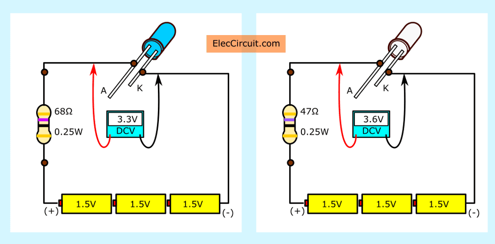
We can also make the same circuit using two aa size 1.5v batteries. For a white led, the forward conduction voltage and the forward current are 3.6v and 20 ma, respectively. Fully assembled 1.5v led flashlight.
5) illuminate 1 watt led with a 1.5v aaa cell. Choosing the resistor value for led: The transformer boosts the input.
Oscilloscope probe at the collector pin of the npn transistor, shows nice sharp current spikes with 24khz. Guido which includes additional features such over charge and low charge cut off for the battery and with a schmidt trigger. The 9v battery served as my 9v power supply, one aa battery made a 1.5v power supply and three aa batteries bundled together made a 4.5v (1.5v + 1.5v + 1.5v = 4.5v) power supply.
Each part ought to be placed and connected with other parts in specific way. Led bd gun sense hod a 5v 12v gnd c b 12v 5v c b a gnd 30 10 30 10 12v 5v 40 20 40 20 c b 70 a 50 50 70. The above diagram shows a 3v led circuit, in this circuit there are two aa cells are used.
It s electrifying cutaway diagram of a torch physical science primary science teaching science. When you are operating an led with 3v you have to use minimum 10 ohms resistor. The following solar powered garden light was designed by mr.
This ensures that the connected battery is never allowed to charge or discharge beyond unsafe levels. Simple led torch circuit diagram. So we must use resistor in series with the led to limit the current flowing through the led.
Led torch light circuit electronics projects electronic schematics electronic circuit projects. The other side has three low voltage pins (ground, vcc, and signal) which connect to the arduino. To make the power supplies i just soldered some wire onto the ends of the batteries i had bought so that i could easily attach the leds to them.
1.5v led booster circuit, joule thief, 1.5v led flashlight. 17 torch taser wiring diagram diy. On the toroid core, i wound 10 turns of #26 wire wrapping wire, pulled out a center tap, and wound another 10 turns.
Connecting it in the same circuit (2n4401, 330 ohms, white led) with a 1.5 volt power supply, i saw that the led lit up, but not as bright as with the bobbin core, but then again, i had only put 20 turns on the toroid. We have one red 5mm round top led that we want to wire up to the vehicle and have already found where we will take our power and ground from in the vehicle for the 12v source. In the 5th design let's learn how to illuminate a 1 watt led using a 1.5 aaa cell for a reasonable amount of time.the circuit is obviously based on boost driver technology, other wise driving such a huge load w such minimal source is beyond imagination.
1.5v solar garden light with enhanced features. Pin on electronics mini projects. The rl solder pad is the reverse 1.5v solder pad for the reverse lights.
Coin #1 30 5v gnd 32 30 50 test 75 d5 main vol gnd sh 80 vcc 50 1p holder coin led 2p holder. At the heart of this circuit is a little coil which you wind yourself. Circuit diagram of solar garden light.
When sunlight falls on the solar cell during daytime, the solar cell charges the rechargeable battery and turns led1 ‘off.’. Hopefully those looking for practical information on electrical circuits and wiring led components found this guide first. High power led flashlight circuit with 1 5v aa battery led power led torch light.
3 volt basic led circuit with 10 ohms resistor. The fl solder pad is the forward 1.5v solder pad for the front lights.

Bicycle LED Light Circuit Using a Single 1.5V Cell

Bicycle LED Light Circuit Using a Single 1.5V Cell Circuit Diagram Centre

1.5V battery powers whiteLED driver MAX1722, MAX4073

Run LED Super Brightly By A Single 1.5V Battery..1.5V LED Circuit..Joule Thief Circuit..[Hindi
1.5V 555 LED Driver Experiment

1.5v LED flashlight circuit HP PHOTOSMART PRINTER

1 5v One Battery Led Light Flasher Circuit Diagram Wiring View and Schematics Diagram

1 watt LED driver circuit 1.5V input, Modified Joule thief Circuits DIY

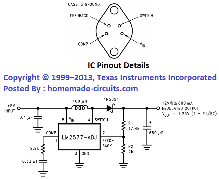
1.5V to 12V DC Converter Circuit for LEDs Homemade Circuit Projects

How to use LED circuit in basic ways

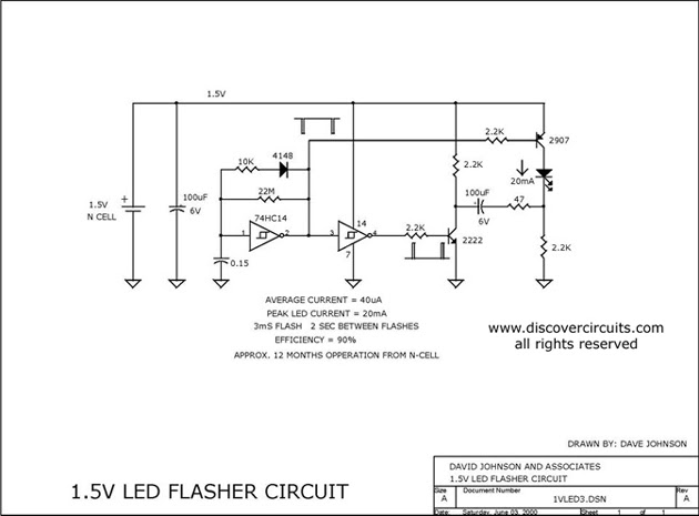
1.5V battery cell LED flasher circuit diagram

electronic circuits 1.5V LED FLASHER VERSION A

White LED on 1.5 v Supply Digital Lab

batteries White LED powered at 1.5V Electrical Engineering Stack Exchange


